RVT_ELEC_01101 Test Free, RVT_ELEC_01101 Exam Pass4sure
Wiki Article
BTW, DOWNLOAD part of TorrentVCE RVT_ELEC_01101 dumps from Cloud Storage: https://drive.google.com/open?id=1KQC5hNmRSBV9--qcH2ZR-4q7W_r7Vcvr
Our website offer you the latest RVT_ELEC_01101 dumps torrent in pdf version and test engine version, which selected according to your study habit. You can print our RVT_ELEC_01101 practice questions out and share the materials with your classmates and friends. The test engine version is a way of exam simulation that helps you get used to the atmosphere of RVT_ELEC_01101 Real Exam and solve the problems with great confidence.
Autodesk RVT_ELEC_01101 Exam Syllabus Topics:
| Topic | Details |
|---|---|
| Topic 1 |
|
| Topic 2 |
|
| Topic 3 |
|
| Topic 4 |
|
| Topic 5 |
|
>> RVT_ELEC_01101 Test Free <<
First-hand Autodesk RVT_ELEC_01101 Test Free: Autodesk Certified Professional in Revit for Electrical Design
In today's technological world, more and more students are taking the Autodesk RVT_ELEC_01101 exam online. While this can be a convenient way to take a RVT_ELEC_01101 exam dumps, it can also be stressful. Luckily, TorrentVCE's best Autodesk RVT_ELEC_01101 Exam Questions can help you prepare for your RVT_ELEC_01101 certification exam and reduce your stress.
Autodesk Certified Professional in Revit for Electrical Design Sample Questions (Q13-Q18):
NEW QUESTION # 13
Refer to exhibit.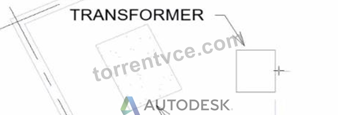
An electrical designer wants to place electrical equipment on the pad.
How should the component be aligned to the pad before placement?
- A. Start the Align tool. tab to select the object edge, and then select the equipment edge.
- B. Start the Align tool and select the edges to be aligned.
- C. Place the cursor over an edge of the object and then press Spacebar.
- D. Place the cursor anywhere over the object and then press Spacebar.
Answer: C
Explanation:
In Autodesk Revit, when placing electrical equipment such as transformers, disconnects, or switchboards onto a pad or foundation, precise alignment is essential for accurate coordination with architectural and structural elements. During component placement, Revit provides an intuitive way to align an object before final placement using the Spacebar in combination with the object's edges.
When the cursor is hovered over an edge of the component (not just anywhere on it) and the Spacebar is pressed, Revit cycles the component's orientation, rotating it 90 degrees around its insertion point each time. This technique allows the designer to visually align the equipment's orientation with the pad or architectural geometry before clicking to place it.
According to the Autodesk Revit MEP User's Guide under "Placing and Modifying Components":
"While placing a component, move the cursor over an edge and press the Spacebar to rotate the element incrementally. This method helps align electrical or mechanical equipment with nearby reference geometry before placement." This method is ideal for electrical designers positioning pad-mounted equipment, ensuring that components such as transformers or switchgear are oriented precisely to site geometry, conduit routes, or building walls.
NEW QUESTION # 14
Refer to exhibits.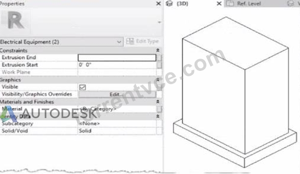
When loaded into a project, the family displays as below in plan view.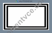
The electrical designer is satisfied with the line color and weight of the transformer because it matches all other electrical equipment in the project. However, the designer wants the housekeeping pad to display with different line properties as shown below.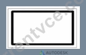
How can this be achieved?
An electrical designer creates a simple family of a transformer with a concrete housekeeping pad using two rectangular extrusions. Both extrusions and their properties within the family editor are shown.
- A. Within the family editor, select the housekeeping pod object and change it from a solid to a void.
- B. Within the family editor, create a new object style subcategory with the desired properties. Assign that subcategory to the housekeeping pad object.
- C. Within the project, right-click and select Override Graphics in View from the context menu. Edit the line properties as desired.
- D. Within the family editor, right-click the housekeeping pad object and select Visibility from the context menu. Edit the line properties as desired.
Answer: B
Explanation:
In Autodesk Revit Electrical Design, when customizing a family-such as a transformer with a housekeeping pad-each element within the family can have its own subcategory under the parent category (in this case, Electrical Equipment). Subcategories are critical for controlling line weight, color, and material properties independently in project views and visibility settings.
The issue described is that the transformer and its concrete pad currently share the same default category (Electrical Equipment) and therefore use identical line weights and colors in plan view. The designer wants the housekeeping pad to display differently - for example, with a lighter or dashed outline.
According to the Autodesk Revit MEP User's Guide (Chapter: Creating and Editing Families):
"To control the visibility or graphical appearance of individual components within a family, create a new Object Styles subcategory under the parent category. You can then assign any solid or void geometry in the family to that subcategory. When loaded into a project, the subcategory can be independently controlled through Visibility/Graphics (VG) settings." This is the exact and recommended workflow for differentiating line appearances between elements in the same family.
Steps to achieve this:
In the Family Editor, open Manage tab ➤ Object Styles.
Under the Model Objects tab, click New to create a new subcategory (e.g., "Housekeeping Pad").
Set the desired line weight, color, or material properties.
Select the housekeeping pad extrusion in the model.
In the Properties palette, under Identity Data → Subcategory, choose Housekeeping Pad.
Reload the family into the project.
You can now modify or control its visibility independently in project views.
Why the other options are incorrect:
A . Change to void: A void removes geometry, not graphical appearance.
B . Override Graphics in View: Applies only in a single view, not globally across the project.
D . Visibility from context menu: Controls whether the object is visible, not its line properties.
Thus, the most efficient, parametric, and Revit-standard method is to use subcategories within the family to apply distinct graphical controls.
References:
Autodesk Revit MEP 2011 User's Guide, Chapter 53: Creating Families - Managing Object Styles, pp. 1248-1251.
Autodesk Revit Architecture 2020 Help, "Assigning Geometry to Subcategories in Families." Smithsonian Facilities Revit Template User's Guide (2021), Section 8.4.1 - Electrical Equipment Family Standards and Subcategories.
NEW QUESTION # 15
A project has 24 branch panel schedules that all need the same formatting changes. What should the electrical designer do?
- A. Select all panel schedules in the Project Browser, right-click and choose Apply Template Properties, and select the desired template.
- B. Use the Manage Templates command to edit and apply the template changes to all panel schedules.
- C. Edit a panel schedule, right-click and choose Duplicate View, and duplicate changes lo desired panel schedules.
- D. Assign the desired view template to the panel schedules in the Properties panel.
Answer: A
Explanation:
To ensure consistency and efficiency when multiple branch panel schedules require identical formatting, Revit allows applying a panel schedule template to one or more schedules simultaneously.
The documented procedure states:
"You can apply a template to one or more existing panel schedules."
And further:
"Select the panel schedule(s).
For Apply Templates, specify the template to apply to the selected panel." This functionality lets an electrical designer select all 24 branch panel schedules in the Project Browser, right-click and apply the desired template to update formatting across all selected schedules in a single operation.
NEW QUESTION # 16
Which feature shows which user created 3n element?
- A. Show History
- B. Worksharing display modes
- C. Gray Inactive Worksets
- D. Worksets dialog
Answer: B
Explanation:
In Autodesk Revit, the Worksharing Display Modes feature allows designers to visually inspect ownership and editing information about elements in a workshared model.
According to the Autodesk Revit MEP User Guide - Chapter 54 "Working in a Team":
"Worksharing Display Modes can be used to visualize the ownership of elements, including which user created or modified them. For example, you can use the Worksharing Display command to show elements by their owner, workset, or checkout status." Thus, this mode identifies which user created or owns an element - making B. Worksharing display modes the correct choice.
Other options:
A . Gray Inactive Worksets: Only shows non-active worksets in gray, not creator info.
C . Show History: Displays synchronization comments, not element ownership.
D . Worksets dialog: Shows ownership of worksets, not individual elements.
NEW QUESTION # 17
Exhibit.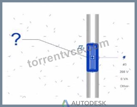
An electrical designer creates a panel schedule. Which Electrical Equipment parameter defines the default name of the panel schedule view?
- A. Mark
- B. Type Mark
- C. Description
- D. Panel Name
Answer: D
Explanation:
In Autodesk Revit for Electrical Design, when a designer creates a panel schedule, the default name of the panel schedule view is automatically derived from the Panel Name parameter of the Electrical Equipment family to which the circuits are assigned.
According to the Revit MEP User's Guide (Electrical Systems section: Panel Schedules):
"When you create a panel schedule, Revit uses the Panel Name parameter of the electrical equipment to define the default schedule name. The Panel Name identifies the distribution panel that supplies the circuits. This name appears in both the Panel Schedule view and in circuit information tags."
- Revit MEP User's Guide, Chapter 17: Electrical Systems - Panel Schedules The Panel Name is a critical electrical equipment instance parameter located in the Electrical - Circuiting group of properties.
It appears in both the Electrical Equipment Properties Palette and the Panel Schedule Header. This name can later be modified manually, but by default, it directly controls the naming convention of the generated schedule.
In contrast:
A . Type Mark - identifies types within the family for documentation and does not control schedule naming.
B . Mark - a unique instance identifier often used for tags, but not for panel schedule view naming.
C . Description - provides descriptive text only for documentation or labeling.
D . Panel Name - correctly defines and drives the default schedule view name for panels and circuits.
When a panel (electrical equipment) is placed in the model and circuits are connected, Revit generates a new Panel Schedule View automatically titled using the value entered in the Panel Name field (e.g., "Panel LP-1"). This ensures consistency between the modeled equipment and the schedule documentation.
Verified Reference Extracts from Revit for Electrical Design Documentation:
Autodesk Revit MEP User's Guide (2011), Chapter 17: Electrical Systems - Creating and Editing Panel Schedules:
"The name of the panel schedule view is determined by the Panel Name property of the electrical equipment." Revit MEP Electrical Design Training Manual, Module: Electrical Equipment and Panel Schedules:
"Panel Name is used by Revit as the default identifier for any panel schedule view created for that equipment."
NEW QUESTION # 18
......
It is important to check the exercises and find the problems. Once you use our RVT_ELEC_01101 study prep to aid your preparation of the exam, all of your exercises of the study materials will be carefully recorded on the system of the RVT_ELEC_01101 exam braindump. Also, you can know your current learning condition clearly. The results will display your final scores on the screen. Also, you will know the numbers of correct and false questions of your exercise. Our RVT_ELEC_01101 test question grading system is designed to assist your study, which is able to calculate quickly. So you don’t need to wait for a long time. The calculating speed of our RVT_ELEC_01101 study prep is undergoing the test of practice. The highest record is up to five seconds. There has no delay time of the grading process. Slow system response doesn’t exist. In addition, the calculation system of the RVT_ELEC_01101 test question is very powerful and stable. We promise that the results of your exercises are accurate.
RVT_ELEC_01101 Exam Pass4sure: https://www.torrentvce.com/RVT_ELEC_01101-valid-vce-collection.html
- Trustable RVT_ELEC_01101 Test Free - Newest Autodesk Certification Training - Pass-Sure Autodesk Autodesk Certified Professional in Revit for Electrical Design ⏮ Download 「 RVT_ELEC_01101 」 for free by simply entering ⏩ www.examdiscuss.com ⏪ website ????Official RVT_ELEC_01101 Study Guide
- 100% Pass Quiz Autodesk - RVT_ELEC_01101 –Trustable Test Free ⏭ Search for ▷ RVT_ELEC_01101 ◁ on ▛ www.pdfvce.com ▟ immediately to obtain a free download ????Reliable RVT_ELEC_01101 Exam Test
- RVT_ELEC_01101 - Autodesk Certified Professional in Revit for Electrical Design Updated Test Free ???? Download ⏩ RVT_ELEC_01101 ⏪ for free by simply entering ➽ www.pass4test.com ???? website ????Printable RVT_ELEC_01101 PDF
- Valid RVT_ELEC_01101 Test Dumps ???? Reliable RVT_ELEC_01101 Braindumps Book ???? Valid RVT_ELEC_01101 Test Dumps ???? ☀ www.pdfvce.com ️☀️ is best website to obtain ⏩ RVT_ELEC_01101 ⏪ for free download ????Valid RVT_ELEC_01101 Test Dumps
- 100% Pass Quiz Autodesk - RVT_ELEC_01101 –Trustable Test Free ???? Search on ⮆ www.verifieddumps.com ⮄ for ▷ RVT_ELEC_01101 ◁ to obtain exam materials for free download ????RVT_ELEC_01101 Actual Exams
- RVT_ELEC_01101 New Real Exam ☣ RVT_ELEC_01101 Exam Pass4sure ???? Printable RVT_ELEC_01101 PDF ???? Search on ➽ www.pdfvce.com ???? for ▛ RVT_ELEC_01101 ▟ to obtain exam materials for free download ????RVT_ELEC_01101 VCE Exam Simulator
- Pass Guaranteed Quiz 2026 RVT_ELEC_01101: Efficient Autodesk Certified Professional in Revit for Electrical Design Test Free ⛳ Search for { RVT_ELEC_01101 } and easily obtain a free download on { www.examcollectionpass.com } ????Exam RVT_ELEC_01101 Study Solutions
- Trustable RVT_ELEC_01101 Test Free - Newest Autodesk Certification Training - Pass-Sure Autodesk Autodesk Certified Professional in Revit for Electrical Design ???? Search for 《 RVT_ELEC_01101 》 on { www.pdfvce.com } immediately to obtain a free download ????RVT_ELEC_01101 High Quality
- Pass Guaranteed Quiz 2026 RVT_ELEC_01101: Efficient Autodesk Certified Professional in Revit for Electrical Design Test Free ???? Search on ⮆ www.examcollectionpass.com ⮄ for ➡ RVT_ELEC_01101 ️⬅️ to obtain exam materials for free download ????Reliable RVT_ELEC_01101 Dumps Free
- Trustable RVT_ELEC_01101 Test Free - Newest Autodesk Certification Training - Pass-Sure Autodesk Autodesk Certified Professional in Revit for Electrical Design ???? Open ▛ www.pdfvce.com ▟ and search for ▶ RVT_ELEC_01101 ◀ to download exam materials for free ????RVT_ELEC_01101 Exam Dumps.zip
- Prepare for sure with RVT_ELEC_01101 free update dumps - RVT_ELEC_01101 dump torrent ???? ▶ www.prepawaypdf.com ◀ is best website to obtain ▶ RVT_ELEC_01101 ◀ for free download ????Answers RVT_ELEC_01101 Free
- bookmark-master.com, www.stes.tyc.edu.tw, www.stes.tyc.edu.tw, hamzatzbd006268.wikigiogio.com, ez-bookmarking.com, rebeccacwud000012.blogaritma.com, myportal.utt.edu.tt, myportal.utt.edu.tt, myportal.utt.edu.tt, myportal.utt.edu.tt, myportal.utt.edu.tt, myportal.utt.edu.tt, myportal.utt.edu.tt, myportal.utt.edu.tt, myportal.utt.edu.tt, myportal.utt.edu.tt, www.stes.tyc.edu.tw, myportal.utt.edu.tt, myportal.utt.edu.tt, myportal.utt.edu.tt, myportal.utt.edu.tt, myportal.utt.edu.tt, myportal.utt.edu.tt, myportal.utt.edu.tt, myportal.utt.edu.tt, myportal.utt.edu.tt, myportal.utt.edu.tt, dianezefv282168.wikifrontier.com, Disposable vapes
P.S. Free & New RVT_ELEC_01101 dumps are available on Google Drive shared by TorrentVCE: https://drive.google.com/open?id=1KQC5hNmRSBV9--qcH2ZR-4q7W_r7Vcvr
Report this wiki page